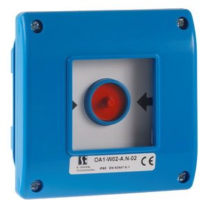
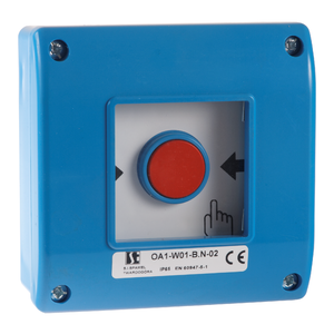
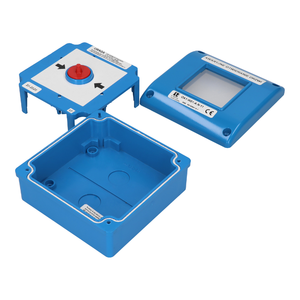
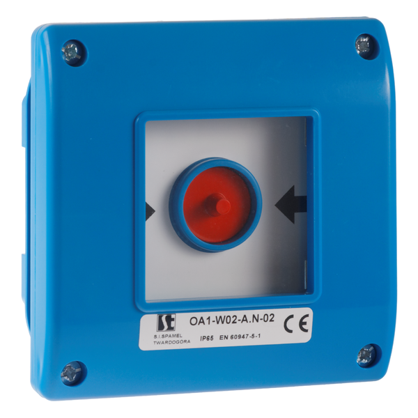
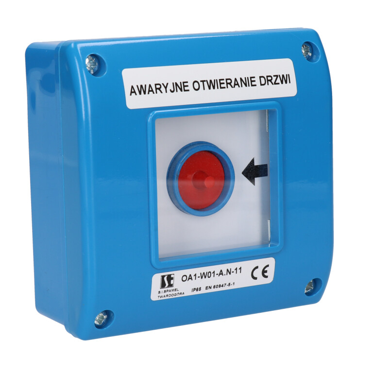
Manual emergency pushbutton OA1 (blue)
Manual emergency pushbuttons OA1
OA1-#-#.N\###
EAN:
Code examples:
OA1-W01-A.N-02-24
On-plaster mounting, 2 NC switches. When the glass is broken the pushbutton is released automatically, type A. Signalling LED 24 V DC.
OA1-W02-B.N-10-230-M
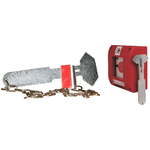
Flush mounting with 1 NO switch. When the glass is broken it is necessary to push the button, type B. Signalling LED 230 V AC. With a hammer.
Manual pushbutton OA1 is intended for applications where emergency manual control is required.
For example, emergency passages which must be opened after breaking the glass element. OA1 is also intended for applications where in an emergency the power supply must be cut off after breaking the glass element.
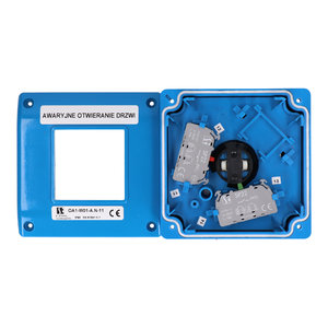
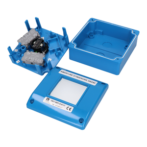
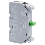
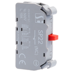
OA1 is available in two versions, type A and B. In type A, the switch is released after breaking the glass in an emergency. In type B, after breaking the glass the momentary pushbutton must be pressed. OA1 is available in flush and surface mounted assemblies. Each enclosure can be fitted with up to three switches SP22-10 (NO) or SP22-01 (NC).
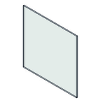
The signal is triggered and sent after breaking the glass (type A) or after breaking the glass and pressing the momentary pushbutton (type B). The alarm signal is reset after replacing the breakable element (glass - ordering code PPOŻ-5701).
When selecting current paths, the selected type (A or B) should be taken into account
TYP A
NO contacts (10, 20, 30): after breaking the glass or removing the cover, the contacts open.
NC contacts (01, 02, 03): after breaking the glass or removing the cover, the contacts close.
Mixed NC/NO contacts (11, 12, 21): after breaking the glass, the NO contacts will open and the NC contacts will close.
TYP B
NO contacts (10, 20, 30): after breaking the glass or removing the cover, the button must be pressed manually - the contacts will close.
NC contacts (01, 02, 03): after breaking the glass or removing the cover, the button must be pressed manually - the contacts will open.
Mixed NC/NO contacts (11, 12, 21): after pressing the button, the NO contacts will close and the NC contacts will open.
| Rated insulation voltage Ui | 500 V |
| Rated continuous current Iu=Ith | 10 A |
| Rated operational current Ie for AC-15 | 2.5 A (230 V) 1.6 A (400/500 V) |
| Rated operational current Ie for AC-13 | 4 A (24 V) 1 A (110 V) 0.25 A (220 V) |
| Degree of protection | IP65 |
| Wire gauge | 2× 1...2.5 mm² (solid) 2× 1...2.5 mm² (stranded) |

